I always wanted to work on 32 bit architectures. I am amazed by their capabilities. I got a chance to work with the National Instruments Embedded Module in my Mechatronic Design Class at CMU 🙂 . I was given a MCB2300 board and a LABView license along with Keil IDE by National Instruments. It uses a LPC 2378 microcontroller from NXP semiconductors. I would like to share my experience on working with this board. In my opinion, its awesome!
The documentation available for this board is quite comprehensive but the errors faced by programmers are scarcely documented. However, they could be resolved by simple tricks. Let me explain controlling a DC motor step by step.
When you install Labview with the embedded module, your startup window should be something like the one shown below:
 Choose Arm Project and Click “Go”
 It would ask you for the type of VI files you would like to create. Choose a blank VI.
 Choose your target board as MCB2300 and save the project.
You should be able to view a new project explorer window with a blank VI.
 You will have to delete the MCB2300 microcontroller board available in the project explorer as there are very limited inputs and outputs that are available to users with that feature. You may right click on your project and configure a new target board.
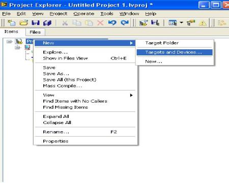 Click on other and choose your microcontroller

 Now select the inputs that you would like to use. You may choose your inputs by a right click on “LPC2378”.
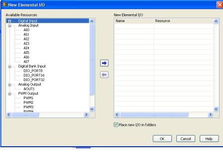
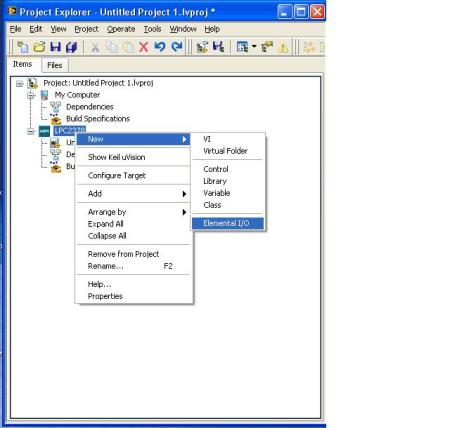 Now choose the PWM channels, digital inputs and outputs of your choice.
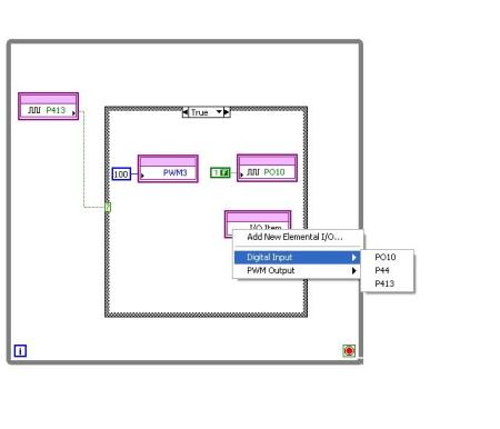
 Open your LABView programming window and “design” your code. You may choose your inputs and outputs as shown in the figure below:
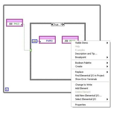
Once you have placed an elemental I/O node, you may choose their usage in the program.
If you would like to configure some of your pins as digital outputs, you may right click on the I/O node and select “Change to Write”. This configures your I/O as a digital output.
Once you have finished programming, click on run to build and compile your code.
You see an output displaying “Running on target”
You may have a look at the video of my DC motor spinning 🙂 🙂 I interfaced a L298 H bridge driver to my microcontroller.




 Posted by yamanoorsai


