Play sound files with Robot See

March 18, 2010

I was trying to learn USB device interfacing using an open source software.  I came across Robot Vision Tool Kit @ http://www.emgrobotics.com

The software seems to be one that has a very small learning curve. I was able to play a song of my choice using the IDE.

This was the command that I used to play my favourite song:

soundplay( “F:\Songs\_Muthumani Malai Spb Sus.wav” )
delay( 5000 )
delay(5000)
delay(5000)
delay(5000)
delay(5000)
The IDE can open only .wav files. So I had to convert the files using an mp3 to wav format converter. All the tutorials are available as videos over You Tube.

IR and LDR sensor strips

February 26, 2010

I have attached the pictures of the IR and sensor strips that I had designed for the robotics workshop.


The chassis design is out!

February 19, 2010

Side view of the chassis without the castor wheel

A close up of the wheel

I have attached some of the pictures of the chassis in its nascent stages. More to come….

Update as on February 25:

I have used 4 spacers to mount the development board.

Back View

Side View


The board has been populated and it is ready

February 8, 2010

PICdevelopment board

The board was populated successfully and most of the functional features of the board have turned out to be successful. I am yet to test one of the two voltage comparators available on the board.

The main features of the board include:

  1. PIC16F877A platform
  2. L293D module ( Can drive 2 geared DC motors or 1 stepper motor)
  3. ULN 2003A module for stepper motors
  4. Voltage comparator circuit for LDR based sensor module
  5. Voltage comparator circuit for IR LED – photodiode based sensor modules
  6. Analog Inputs
  7. Seven Segment Display * 4nos
  8. RS232 port
  9. LED outputs to test the comparators/voltage sensors
  10. 8 LEDs to test the outputs of the individual pins of the controller
  11. Plug and play option — Can test it with simple connecting wires across any pin of the microcontroller
  12. Power supply pins to power other add-on boards

Looking foward for your comments!


Functional Features of my development board

February 4, 2010

It had been a long time since the development board was manufactured. I was able to test some of the features of the board. I am done with the H bridge, RS232 communication and the A/D conversion. All were successful.

I realised the importance of input filters only when I blew up the microcontroller by connecting the 12V DC motor to the power supply that is not provided with input filters!

I tried pulse width modulation with my board and I have included  a video that shows the motor running at slow speed in opposite directions.

Interaction of the PIC with the PC using MikroC routines

The MikroC routines for the PIC microcontroller were handy to test my board. In the picture, I was able to send a data to my PIC and echo it back to the PC!

I am yet to program the correct sequence for energising the sequence of the stepper motor coils.


Building your first development board

November 2, 2009

I had a long chat with one of my friends regarding microcontroller applications and the like.

It never occurred to me that we spend thousands on buying different components for our hobby projects and we discard them after their intended use or construct a different one for another application.

A classical example of using an electronic circuit board on a longer run is your first microcontroller development board.  Be it AVR or a PIC microcontroller, you are going to re-use them for several hobby projects.  Why not develop it as a standard platform?

There are people who sell development boards for PIC and AVR microcontrollers in the market. They provide you with standard interfaces to learn from scratch. For e.g LED Blinking, Seven Segment LED interface, LCD interface, Stepper Motor Driver, Servo Motor Driver etc. One can develop them for himself/herself, step by step.
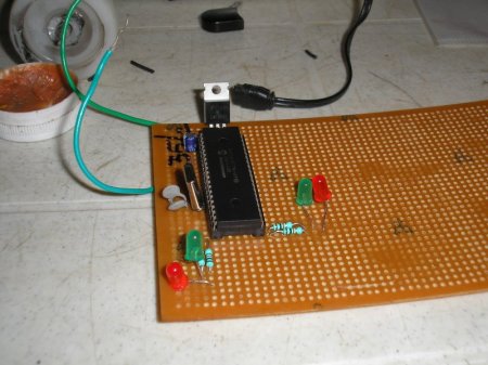
PIC development board

The insert picture shows a PIC 16F877A board developed by me for my hobby projects. It has got the ubiquitous LED interfaced to it. Any hobbyist tests his/her microcontroller board with a standard LED blinking program to start with.

By developing one such board, I learnt interfacing the above mentioned examples. I developed all the standard drivers required for the components, myself. One day, I am planning to bring all the applications together as a product!

Why not try one for yourself?


LM 311 Light activated Switch

September 18, 2009

18 September 2009:

LM311

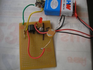
Well, Here is my first sensor that was rolled out for my Line following Robot ‘Cyborg’. It is a Light Detective Resistor (LDR) based circuit where the resistance of the LDR drops when light is incident on it. This results in an LED glowing at the output of the LM311 voltage comparator.

I got the circuit for this comparator from Circuits Today. At present, I am facing some problems with BC107 transistor which acts a switch at the out put of the comparator. I will either replace it or remove it from the picture at the earliest. To know how a voltage comparator works, click here.

I have plans of debugging the worn out transistor, adding up one more sensor for my Cyborg as well as trying this comparator for IR transmitter pair. Watch out for more updates!

19 September 2009:

I removed the transistor and I was able to learn that the transistor while acting as a switch, inverts the output of the comparator i.e., When the LDR resistance drops, the LED goes off and vice versa which is quite opposite to its earlier operation.

I have demonstrated the application of obstacle detection using a simple video. Here, the obstacle reflects the light from the white LED on the surface of  the LDR causing a drop in resistance. This makes the output of the comparator turn high. Eventually the LED switches off!


PIC16F84A based robot

September 2, 2009

Well, I had been working on a DC Motor control for the past few days using the PIC16F84A Platform. I have uploaded two videos. The first one shows the DC Motor operation in the forward and reverse direction.

I assembled those DC Motors on to a acrylic sheet and clamped them to run them in the forward and reverse directions with a pause. Wow!

I have also shown the LED indicating the time duration for which the DC Motors keep rotating in the either direction. Well, there has been some problems with the balancing. I am trying to add a castor in the back side also!