Trick to draw circular PCB outlines in Eagle

December 26, 2017

If you haven’t used the Eagle PCB design tool lately, you will be surprised to learn that it has underwent a major update since it was acquired by Autodesk.

Eagle’s license model has been switched over to a subscription service and I am liking the experience so far. I am able to get the latest updates of the software (unlike earlier, the updates are quite frequent). I am currently using Eagle 8.5.x and it comes with the “Push and Shove” feature that automatically pushes signal traces while routing your PCB.

PCB Outlines

I was working on a circular PCB for building something like a fidget spinner. I assumed that I could draw circular PCB outlines by drawing a simple circle.

Circle_snapshot

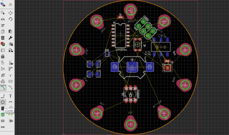
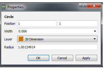
Circle feature in Eagle PCB

Being able to draw circular outlines can make your life easy. For example: You could draw a random circle and specify its radius, center etc (similar to Mechanical CAD tools).

Circle_Radius

It turns out that the software considers this an error. When I started to route the PCB, the automated DRC check ignored glaringly obvious errors.

eagle_2017-12-26_19-54-44

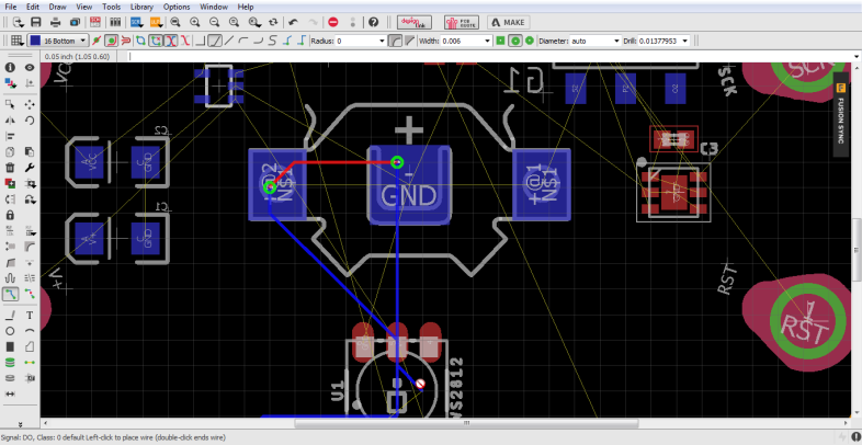
Errors resulting from the Circular Outline

In the above snapshot, you will note that I am able to route traces over PCB pads and the cursor indicates bad news.

After wasting some time, I found out from this forum thread that I need to draw my outline using arcs.

In Eagle, drawing an arc is a three step process:

  • Specify the starting point
  • Move the cursor to specify the arc radius
  • Draw the arc

It is definitely confusing and imagine drawing a “closed circle” using arcs. It can be frustrating.

I eventually managed to find a simple solution that involves combining arcs to draw circular outlines. Check it out!

I am no video expert. I made this video using basic screen capture tools. I look forward to hearing your tips on improving the video.

I really hope Autodesk simplifies creation of non-standard outlines. Did you have a similar experience? Drop your thoughts in the comments section!

My design is off to OSH Park. What manufacturing house do you use for your designs? I will share my build in upcoming blog posts.


PIC JDM Programmer

March 1, 2010

I must thank my friend Sathish who has developed this cute little JDM PIC programmer. This is the smallest programmer that I have ever used for a PIC.

PIC JDM Programmer

He has used the schematic from Olimex as a reference.

Please find the link below:

http://www.olimex.com/dev/images/pic-pg2c-sch.gif


The board has been populated and it is ready

February 8, 2010

PICdevelopment board

The board was populated successfully and most of the functional features of the board have turned out to be successful. I am yet to test one of the two voltage comparators available on the board.

The main features of the board include:

  1. PIC16F877A platform
  2. L293D module ( Can drive 2 geared DC motors or 1 stepper motor)
  3. ULN 2003A module for stepper motors
  4. Voltage comparator circuit for LDR based sensor module
  5. Voltage comparator circuit for IR LED – photodiode based sensor modules
  6. Analog Inputs
  7. Seven Segment Display * 4nos
  8. RS232 port
  9. LED outputs to test the comparators/voltage sensors
  10. 8 LEDs to test the outputs of the individual pins of the controller
  11. Plug and play option — Can test it with simple connecting wires across any pin of the microcontroller
  12. Power supply pins to power other add-on boards

Looking foward for your comments!


Functional Features of my development board

February 4, 2010

It had been a long time since the development board was manufactured. I was able to test some of the features of the board. I am done with the H bridge, RS232 communication and the A/D conversion. All were successful.

I realised the importance of input filters only when I blew up the microcontroller by connecting the 12V DC motor to the power supply that is not provided with input filters!

I tried pulse width modulation with my board and I have included  a video that shows the motor running at slow speed in opposite directions.

Interaction of the PIC with the PC using MikroC routines

The MikroC routines for the PIC microcontroller were handy to test my board. In the picture, I was able to send a data to my PIC and echo it back to the PC!

I am yet to program the correct sequence for energising the sequence of the stepper motor coils.


PCB drill tool

January 26, 2010

I must thank my friend “NASA” Satish on this occasion. I had some problems with my development board. The manufacturer didn’t drill the mounting holes for a few components.  My friend suggested that I buy a hand drill available at Sunrise Electronics, Coimbatore. I never knew that a hand drill for PCB drilling was available at INR 100. I strongly recommend this tool to all hobbyists. This drilling tool comes with drill bits of 6 different diameters.

The drill bit is quite easier to mount. Just take a bit and lock it inside the holder. You drill the hole by pressing the tool from top. The threaded part of the tool gives rotary motion to the holder. Drilling has never been this easy!

Cheers!


She(Development Board) is ready

January 24, 2010

Finally the board that I had developed is ready. I tested the function of the board with simple PWM program. I provided the output to capture the output using a LED. Though it may not look like a pulse width modulated output, I am happy that the basic functionality of the board is a great success. I believe that the other functionalities are also successful.  I plan to make it open source when the board is fully functional.

I am also enclosing a few photographs of my development board


Mistakes that can be a learning experience

January 16, 2010

It is a general opinion that one must learn from his takes. Well, I had this medicine and it tastes bitter 🙂

Prototype of my first board

I had mentioned in my previous post about my efforts to develop a PIC development hardware. The efforts are on.

I took a print out of the copper layer using a pdf file. The pdf file reduced the pitch and altered the dimensions of the board.  Let’s hope for the best from the boards that have been ordered after correcting these errors.