My Own COM Port GUI

June 9, 2010

I am going to  write about the GUI that I developed for sending data to my PIC development board. I used Liberty BASIC Gold version to develop this GUI.

You may download the demo version for free at http://www.libertybasic.com/. However, there are certain limits for the software and you have to register for a Gold version to enjoy all the features of the software.  The programming window of the software looks like the one shown in the picture below. There are tutorials available in the software which may be accessed as shown in the picture below. You may learn to open a GUI window, add buttons and consequently handle events upon button click  using the simple tutorials. These are  essential elements for our COM port recipe. When you are done with the tutorials,  you would be capable enough to design a small interface as shown in the picture below: Once you are done adding buttons, you must add a functionality to the buttons. For eg: I have added the close window option to Quit button. I am sending a string of information to my controller when I press either of the Forward, Reverse or Neutral buttons.

The algorithm for the same is as follows:

1) Open COM port

2) Send string

3) Close COM port.

Close button press event handle

Note: You have to close the event handles properly once you are done with handling the event of a button press or your code may end with bugs.

The algorithm at the PIC microcontroller end  to receive ASCII string from your computer is as follows:

1) Initialise ports and Set the Baud rate

2) If data received, read the data.

3) If string x is received, move forward

4)If string y is received, move reverse

5)If string z is received, move to neutral position

6) Go to step 2

Please note that I am trying to control a servo motor through serial port.  If you would like to know the operation of a servo motor, please refer to the following link.

I used the MikroC compiler to write the code for serial port communication and servo motor control.

unsigned short i;
void main()
{
TRISB = 0x00;
USART_init(19200);
while(1)
{ if (USART_Data_Ready())
{
i = USART_Read();
i = i-48;
if( i ==1)
{
PORTB = 1;
delay_us(1500);
PORTB = 0;
delay_ms(18);
delay_us(500);
delay_ms(1000);
}
else if(i==0)
{
PORTB = 1;
delay_us(1250);
PORTB = 0;
delay_ms(18);
delay_us(750);
delay_ms(1000);
}
else if(i==2)
{
PORTB = 1;
delay_us(1750);
PORTB = 0;
delay_ms(18);
delay_us(250);
delay_ms(1000);
}
else
{
}
}
}
}

Please note that the baud rate was 19200 bps, 1 stop bit, no parity, no hardware control and the number of bits transmitted was 8.

When you are done coding your PIC, you may create an exe file for your application as follows: You may download the GUI that I developed from the following location.

You may also have a look at my video of operating my servo motor through serial port.


PIC JDM Programmer

March 1, 2010

I must thank my friend Sathish who has developed this cute little JDM PIC programmer. This is the smallest programmer that I have ever used for a PIC.

PIC JDM Programmer

He has used the schematic from Olimex as a reference.

Please find the link below:

http://www.olimex.com/dev/images/pic-pg2c-sch.gif


The board has been populated and it is ready

February 8, 2010

PICdevelopment board

The board was populated successfully and most of the functional features of the board have turned out to be successful. I am yet to test one of the two voltage comparators available on the board.

The main features of the board include:

  1. PIC16F877A platform
  2. L293D module ( Can drive 2 geared DC motors or 1 stepper motor)
  3. ULN 2003A module for stepper motors
  4. Voltage comparator circuit for LDR based sensor module
  5. Voltage comparator circuit for IR LED – photodiode based sensor modules
  6. Analog Inputs
  7. Seven Segment Display * 4nos
  8. RS232 port
  9. LED outputs to test the comparators/voltage sensors
  10. 8 LEDs to test the outputs of the individual pins of the controller
  11. Plug and play option — Can test it with simple connecting wires across any pin of the microcontroller
  12. Power supply pins to power other add-on boards

Looking foward for your comments!


Functional Features of my development board

February 4, 2010

It had been a long time since the development board was manufactured. I was able to test some of the features of the board. I am done with the H bridge, RS232 communication and the A/D conversion. All were successful.

I realised the importance of input filters only when I blew up the microcontroller by connecting the 12V DC motor to the power supply that is not provided with input filters!

I tried pulse width modulation with my board and I have included  a video that shows the motor running at slow speed in opposite directions.

Interaction of the PIC with the PC using MikroC routines

The MikroC routines for the PIC microcontroller were handy to test my board. In the picture, I was able to send a data to my PIC and echo it back to the PC!

I am yet to program the correct sequence for energising the sequence of the stepper motor coils.


She(Development Board) is ready

January 24, 2010

Finally the board that I had developed is ready. I tested the function of the board with simple PWM program. I provided the output to capture the output using a LED. Though it may not look like a pulse width modulated output, I am happy that the basic functionality of the board is a great success. I believe that the other functionalities are also successful.  I plan to make it open source when the board is fully functional.

I am also enclosing a few photographs of my development board


Pneumatic Cylinder Sequence Control

November 5, 2009

This project won me the first prize at the mini project exhibition held on the eve of Engineers day (September 15 2007). The concept behind the project is the use of a microcontroller to control the actuation of two single acting spring return cylinders.  For starters, I am explaining the entire project with the help of circuits that is hand drawn.

I am starting with the explanation of the electronic circuitry involved.

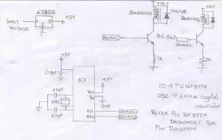
I used a 8051 microcontroller. The power supply circuit and the microcontroller pin diagram is shown in the figure below.  I have explained the same using a PIC16F877A. Two pins of the controller were used as the control for the relay actuation sequence.

Microcontroller Circuit

PIC16F877A based circuit to actuate relays

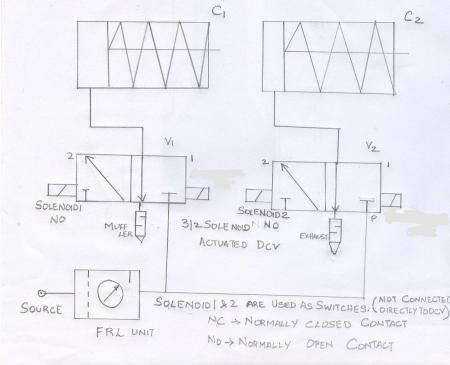
The pins were connected to the base of a BC547 transistor. Here, the BC547 transistor acts a switch. When the base of the controller is provided a “high” signal from the controller, the circuit closes and the 12V relay is actuated. As soon as the relay is actuated, the “normally closed” contact of the relay “opens” and the “normally open” contact of the relay “closes”. Two 3/2 solenoid operated direction control valves were used in the setup.  The terminals of the solenoid which is responsible for extending the cylinder are connected to the normally open ends of the relay. The pneumatic circuit diagram is shown in the figure below: Pneumatic circuit The single acting cylinders could be replaced by two double acting cylinders. An interlocking circuit where one cylinder remains retracted while the other is extended could also be developed easily. This circuit could be controlled for any timing sequence altering the delay between the extension of the cylinders. This is controlled in the program.
Update: The practical application of this circuit could be in a CNC machine. The clamping of a job and the door lock could be interlocked with a simple program using a similar circuit with double acting cylinders.


Building your first development board

November 2, 2009

I had a long chat with one of my friends regarding microcontroller applications and the like.

It never occurred to me that we spend thousands on buying different components for our hobby projects and we discard them after their intended use or construct a different one for another application.

A classical example of using an electronic circuit board on a longer run is your first microcontroller development board.  Be it AVR or a PIC microcontroller, you are going to re-use them for several hobby projects.  Why not develop it as a standard platform?

There are people who sell development boards for PIC and AVR microcontrollers in the market. They provide you with standard interfaces to learn from scratch. For e.g LED Blinking, Seven Segment LED interface, LCD interface, Stepper Motor Driver, Servo Motor Driver etc. One can develop them for himself/herself, step by step.

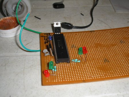
PIC development board

The insert picture shows a PIC 16F877A board developed by me for my hobby projects. It has got the ubiquitous LED interfaced to it. Any hobbyist tests his/her microcontroller board with a standard LED blinking program to start with.

By developing one such board, I learnt interfacing the above mentioned examples. I developed all the standard drivers required for the components, myself. One day, I am planning to bring all the applications together as a product!

Why not try one for yourself?


Reading Serial Port Data using VISA in Labview

September 10, 2009

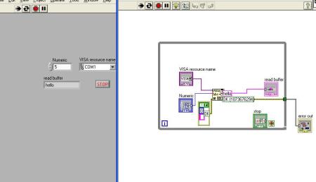
I had been feeling so sleepy today that I wanted to try VISA (Virtual Instrumentation Software Architecture) to read the data from my PIC16F877A microcontroller using the LabVIEW software. Well I did it in a whopping 5 minutes!

Well, the data that is being read is shown in the snapshot below:

LAbview serial port communication

The number of bytes to be read is controlled by the user. However, the data that is being read is displayed in a marquee sequence.

For e.g: When you choose to read a 4 byte data, the fourth byte of data is replaced by a byte with a  shift towards the right when the latest byte of  data arrives at the first bit (left side).

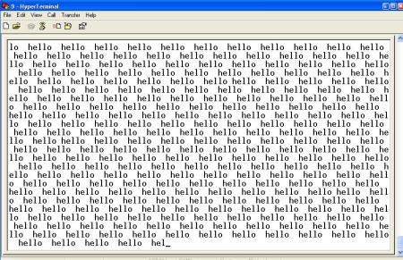
So your data hello would be read as : h –> he –> hel —> and so on. I captured a snapshot when the indicator read ‘hello’ 😉

However, my reading process was interrupted by an error log created everytime. I added an error out constant which made things smooth!

Woohoo!

I shall try adding some features to this VI in future.


PIC serial communication

September 8, 2009

24 July 2009:

I am currently working on serial communication using PIC16F877A. More details to follow.

September 08 2009:

This shows how I procrastinate things. Finally, I achieved it. I have communicated to my PC using PIC16F877A. It took more than 48 hours to achieve this task!

Well! My two cents on serial communications is “Datasheet is your Bible!’

Never digress from the procedure mentioned in the datasheet!

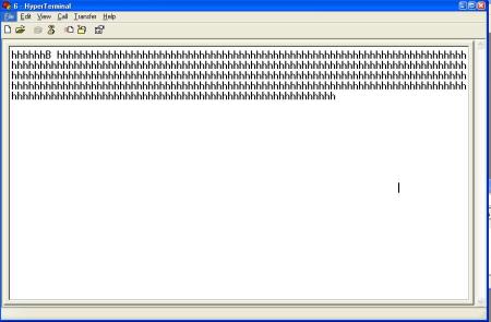
In the rudimentary stages, I blindly followed the rules and I was able to send the letter ‘h’ to the hyper terminal. But I faced problems with the set baud rate of my microcontroller and it was sending some unknown characters to the terminal.

The frequency of my crystal oscillator was 11Mhz. Hence my Baud rate value would be 71 which was arrived at by using the formula given in the data sheet.

The screen shot of the letter h being received at the terminal is shown below!

First data from uC

I had to follow this procedure to declare an array containing the data ‘hello world’ which gives the satisfaction of winning a noble prize to any rookie.

The word ‘hello’ over the terminal  is shown below:

Hell from uCThe Pic 16F877A data sheet can be downloaded from the Microchip website!

The code used for serial port communication was:

#include<pic.h>

void delay(unsigned int n)

{

while(n- -);

}

unsigned char data[17]=” hello world ‘”;

int i;

void main()

{

TRISC = 0x80;

SYNC =0;

SPEN = 1;

TXIE = 1;

TX9 = 0;

BRGH = 1;

GIE = 1;

PEIE = 1;

RCIE = 0;

SPBRG = 71;

while(1)

{

TXEN=1;

}

}

void interrupt isr(void)

{

for(i=0; i<=6; i++)

{

TXREG = data[i];

delay(500);

}

}

Happy Programming!
#include<pic.h>
void delay(unsigned int n)
{
while(n–);
}
unsigned char data[17]=” hello world””;
int i;
void main()
{
TRISC = 0x80;
SYNC =0;
SPEN = 1;
TXIE = 1;
TX9 = 0;
BRGH = 1;
GIE = 1;
PEIE = 1;
RCIE = 0;
SPBRG = 71;
while(1)
{
TXEN=1;
}
}
void interrupt isr(void)
{
for(i=0; i<=6; i++)
{
TXREG = data[i];
delay(500);
}
}